
Module 3. EMG Technique
How to collect electromyography (EMG) for observing MEPs from TMS, and troubleshoot biological and electrical noise in EMG signals.
Overview
EMG is used to record electrical muscle activity, including motor evoked potentials (MEPs) produced by TMS. In PREP2, EMG signals are recorded from the extensor carpi radialis (ECR) and first dorsal interosseous (FDI) muscles of the paretic upper limb.
First, prepare the skin and securely place the surface electrodes.
Two electrodes are required for each muscle.
For good quality EMG:
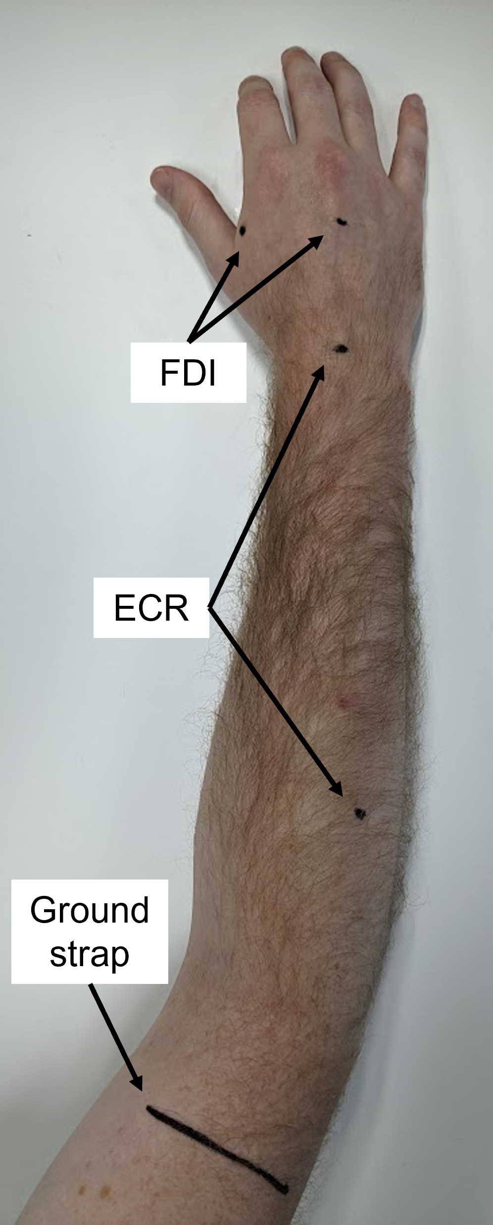
Locate the electrode sites as described below; avoid broken skin.
Shave hair from the electrode sites.
Clean the skin with an alcohol wipe.
Lightly abrade the skin with prep tape.
Centre each electrode on the prepared.
Press each electrode firmly onto the skin and secure with tape if needed.
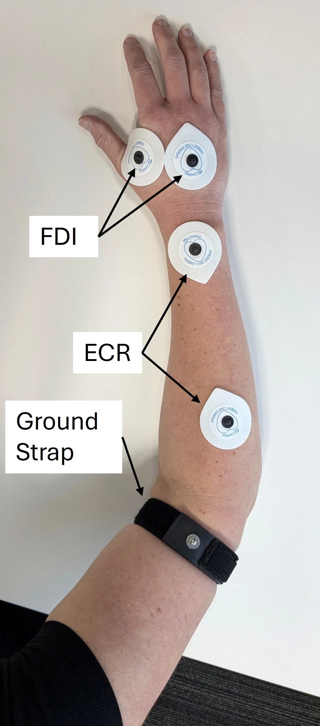
Use electrode leads to connect the electrodes to the EMG unit, ensuring they are securely attached at both ends.
Channel 1: ECR
Channel 2: FDI
Once the electrodes are connected, you will proceed to stimulation as described in module 4 TMS Protocol.
The remainder of this module covers identifying and troubleshooting EMG noise. High-quality EMG is essential because biological or electrical noise can obscure MEPs, producing an undetermined MEP status and preventing a PREP2 prediction.
Extensor Carpi Radialis (ECR) is a muscle that lies in the posterior forearm and primarily extends the wrist. Place the electrodes as follows:
Place one electrode over the muscle belly.
Place the second electrode on the dorsal wrist, centred between the radial and ulnar styloid processes.
To locate the ECR muscle belly, ask the patient to extend the wrist with a closed fist, if able, and palpate the indicated forearm area. If wrist extension is not possible, palpate the brachioradialis along the radial forearm and roll your fingers medially onto the extensors, which should lead to palpating the ECR muscle belly. The ECR lies along an imaginary line from the lateral epicondyle of the humerus to the base of the second metacarpal.
First Dorsal Interosseous (FDI) is a muscle in the hand that primarily abducts the index finger. Place the electrodes as follows:
Place one electrode over the muscle belly.
Place the second electrode at the center of the dorsum of the hand.
The FDI muscle belly is the fleshy area just proximal to the web space between the thumb and index finger on the dorsal hand. If possible, palpate it while the patient abducts the index finger. Place the electrode over the muscle belly, not the web space.
Use a ground electrode or strap to reduce environmental electrical noise.
If using a ground electrode, place over a bony area, such as the lateral humeral epicondyle.
If using a ground strap, place it around the arm just above the elbow, with the metal pin visible, facing outward, and not touching the skin.
Noise-Free EMG Traces
Noise-free EMG appears flat except for the stimulus artefact and an MEP. The artefact is generated by TMS–coil discharge and is problematic only if prolonged, as described later.
The examples below show the target appearance of noise-free EMG traces. This is what you should be aiming for with your EMG traces.
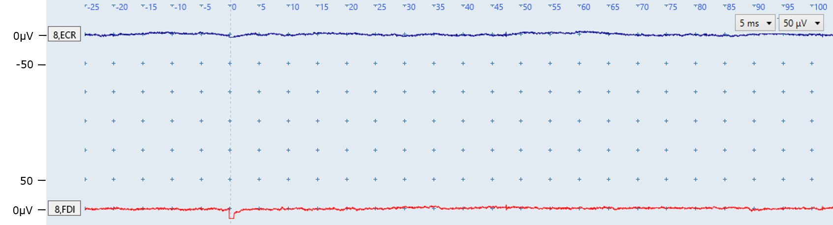
Figure A: Both traces are flat and noise-free, with no MEPs. The small deflection at 0 ms in the red FDI trace is the stimulus artefact from TMS-coil discharge.
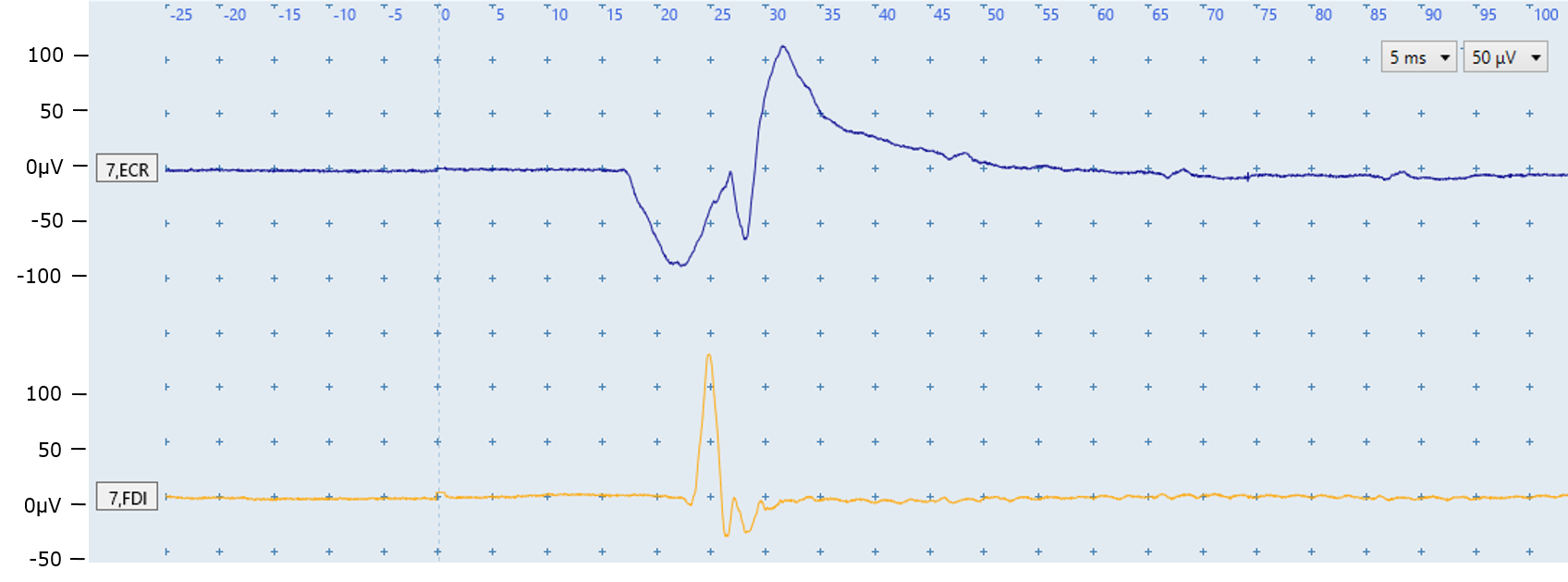
Figure B: The ECR (top) and FDI (bottom) traces are flat and noise-free, with an MEP in each trace. MEP Identification is covered in modules 5 (Simple MEP identification) and 6 (Challenging MEP identification).
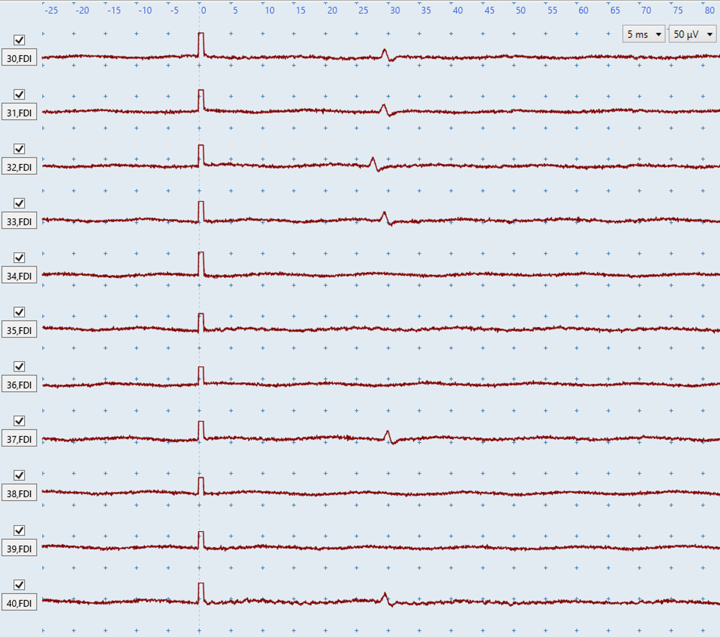
Figure C: The FDI contains several small MEPs (~20 microvolts), visible only because the EMG is noise-free. Even minor biological or non-biological noise could obscure them and cause an incorrect or undetermined MEP-status determination.
EMG noise is broadly defined as either biological or non-biological noise, and both may occur together. The first step to troubleshooting any noise is to determine whether it is biological or non-biological, and then use the relevant troubleshooting section below:
Biological noise
Muscle activation
Sporadic motor units firing
Biological Noise
Non-biological noise
Electrical noise in both channels
Electrical noise in one channel
Prolonged stimulus artefacts
Check that the EMG is free of biological noise. Biological noise can obscure small MEPs which causes an incorrect MEP− classification, or it can resemble an MEP which causes an incorrect MEP+ classification.
The two main sources of biological noise are muscle activation and sporadic motor-unit firing.
Muscle activity
Muscle activation occurs when the ECR or FDI is active during stimulation, producing deflections in the EMG traces. Keep both upper limbs fully relaxed and monitor each trial throughout the session. During bilateral facilitation, intentional activation is expected and should not be troubleshooted.
The key feature to distinguish muscle activation noise from electrical noise is that muscle activation noise does not have a regular pattern, as you can see in the examples below.
The following troubleshooting suggestions will help your patient stay relaxed:
Support the hand and arm on a low, soft surface such as a pillow on the lap or bed; elevated hard surfaces may activate the ECR.
Lift and support the wrist and elbow, gently move the arm, and ask the patient to let you take its full weight. Once you have their full weight, gently place the limb back on the pillow and ask them to drop their shoulders.
Ask the patient to take a deep breath, exhale, and drop their shoulders. Use imagery, such as arms floating in warm water, to encourage relaxation.
Position the patient with their shoulder internally rotated so the forearm rests across the body rather than pointing forwards.
Try different supported hand positions, especially for FDI activation; a half-open hand with flexed fingers may help.
Offer a short break after several minutes of stimulation.
Keep the non-paretic upper limb relaxed.
If needed, let the arm hang down beside the chair or side of bed under its own weight; use caution if the patient has an unstable shoulder.
If muscle activity persists after trying the troubleshooting steps above, continue with TMS. Some patients may remain active because of anxiety, inattention, or difficulty understanding the relaxation instructions.
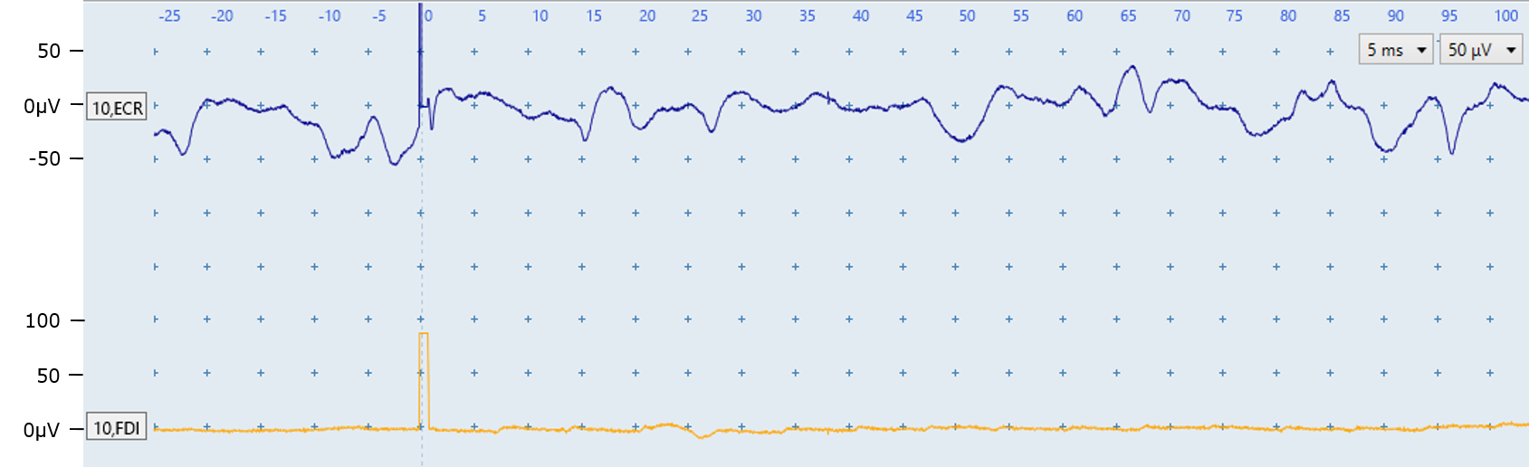
Figure D: The ECR trace (top) shows muscle-activation noise with no MEP. The noise in the ECR trace can be identified as muscle activation because it does not have a regular pattern. The FDI trace is noise-free.
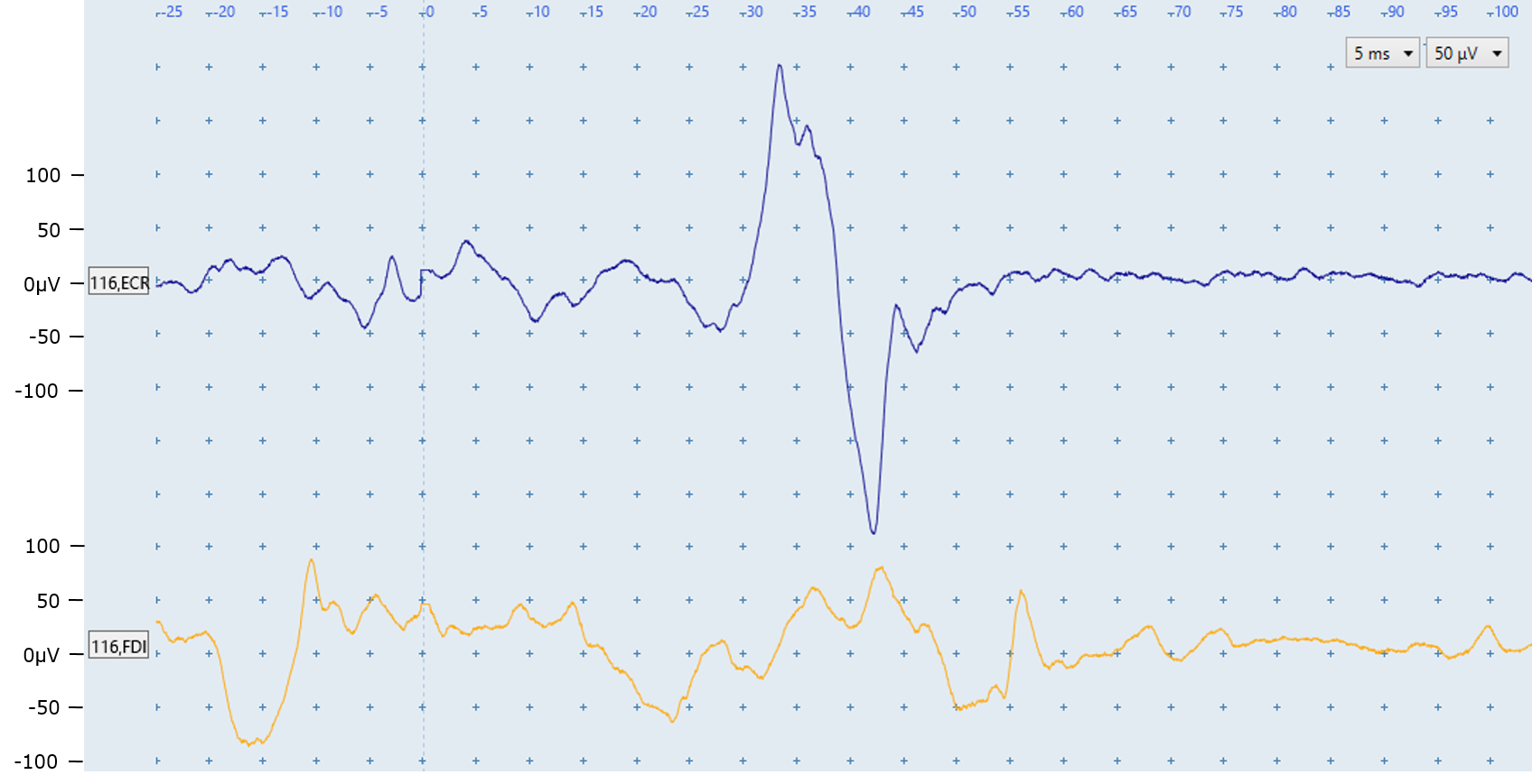
Figure E: Both traces show muscle-activation noise with no regular pattern. An MEP is present in the ECR trace and more information about identifying MEPs in the presence of biological noise is provided in the Challenging MEP identification module. No FDI MEP is present.
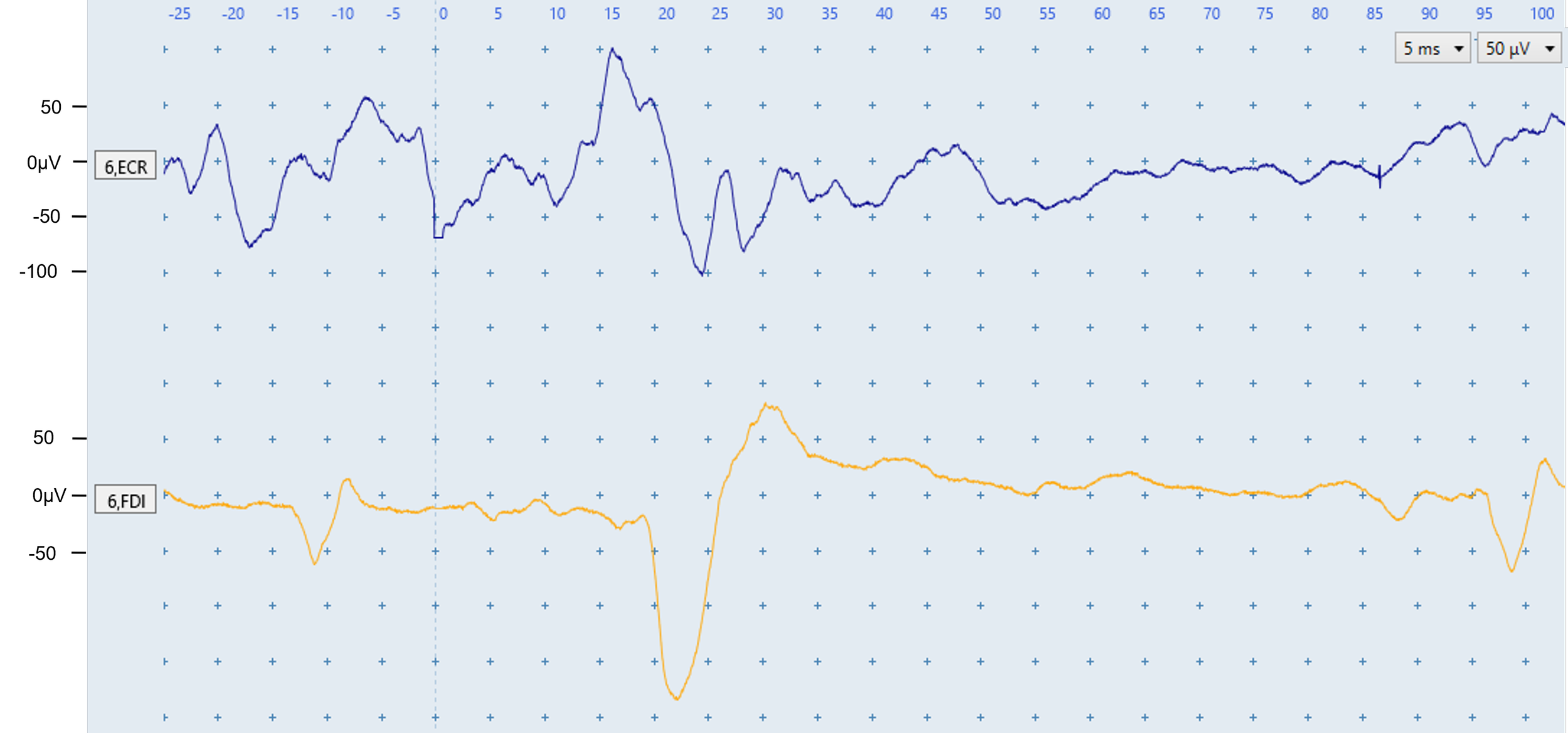
Figure F: The ECR trace shows muscle-activation noise with no pattern. The FDI trace shows low-level activation, an MEP at ~20 ms, and sporadic motor-unit firing at ~−12 and 95 ms. The repeated motor-unit shape and latencies outside the expected FDI MEP window distinguish these responses from MEPs.
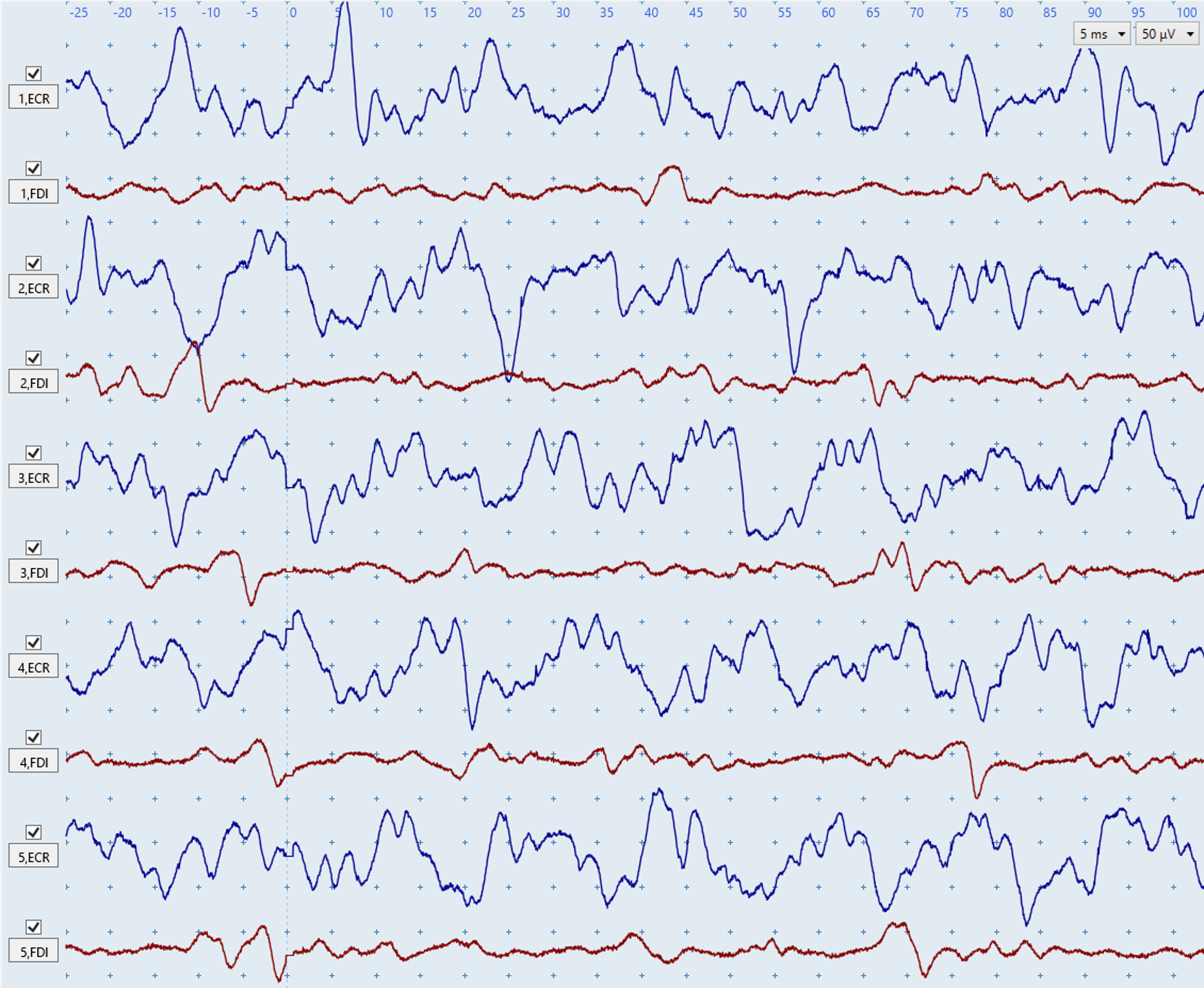
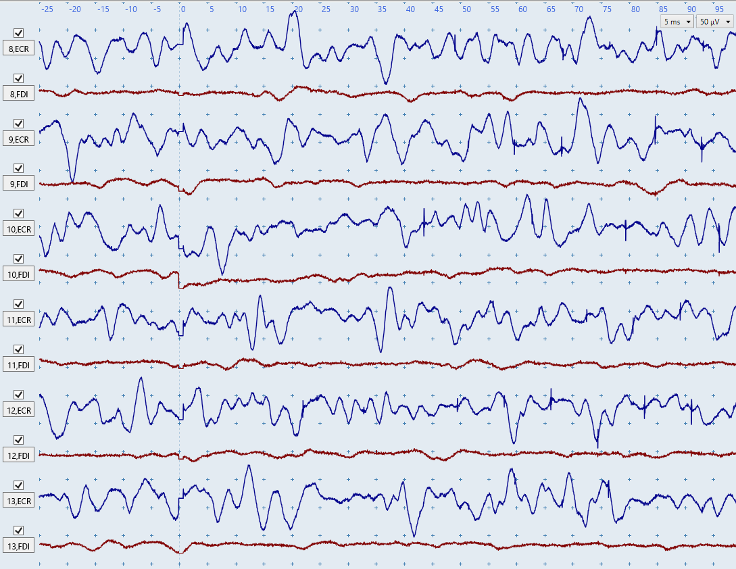
Figures G–H: Both figures show severe, irregular muscle-activation noise in the blue ECR traces. These figures illustrate how biological noise due to muscle activation does not have a consistent shape or rhythm between different traces.The red FDI traces show low-level activation in Figure G and are largely noise-free in Figure H. No MEPs are present because there are no consistent deflections within the expected latency windows (~15–25 ms for ECR; ~20–30 ms for FDI).
Sporadic motor-unit firing
The second form of biological noise is caused by motor units innervating the ECR and/or FDI firing sporadically. A motor unit is made up of a single motor-neuron axon and all of the muscle fibers it innervates. Sporadic motor-unit firing may occur without conscious awareness.
Sporadic motor-unit responses can be identified due to their consistent size and shape in EMG traces, and they typically resemble MEPs. They usually recur within or across traces and occur outside the expected MEP windows (~15–25 ms for ECR; ~20–30 ms for FDI). If a motor unit is firing spontaneously then you will usually see it appear more than once in the trace.
The best way to troubleshoot motor units is to re-position the patient's arms and hands so they are fully supported.
Figure I: The ECR deflections at ~20 and ~100 ms are sporadic motor-unit responses, not MEPs. You can tell these deflections are sporadic motor-unit responses due to their identical shape and the ~100 ms latency. A similar situation is shown in Figure W below. The FDI trace contains a small MEP at ~33 ms and no motor-unit firing.
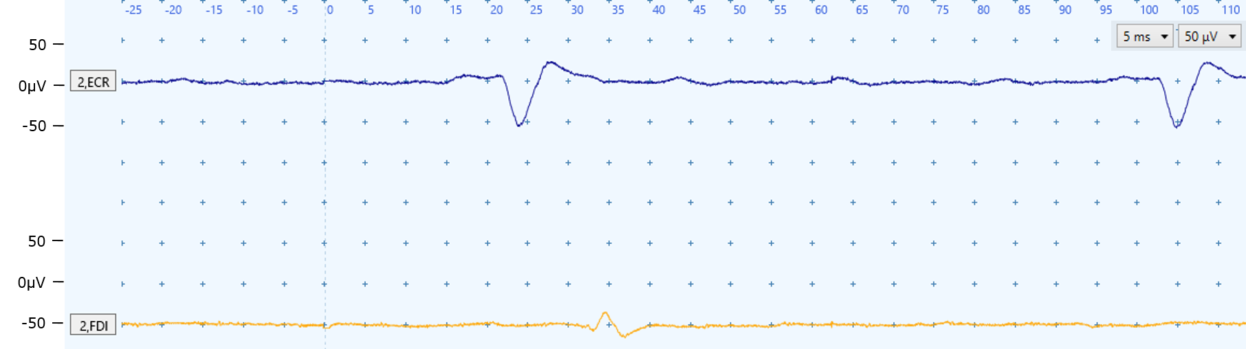
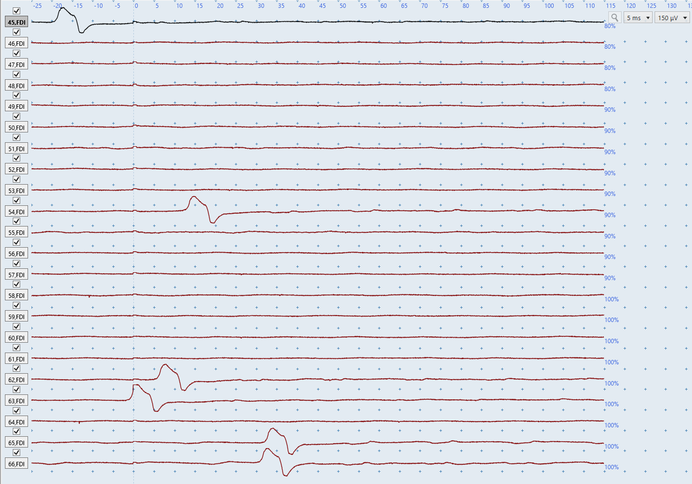
Figure J: You often need to review multiple traces together to distinguish MEPs from sporadic motor-unit firing. The FDI deflections in the final two traces could appear to be MEPs in isolation, but they can be identified as motor-unit responses due to their identical shape to deflections outside the expected MEP windows in earlier traces.
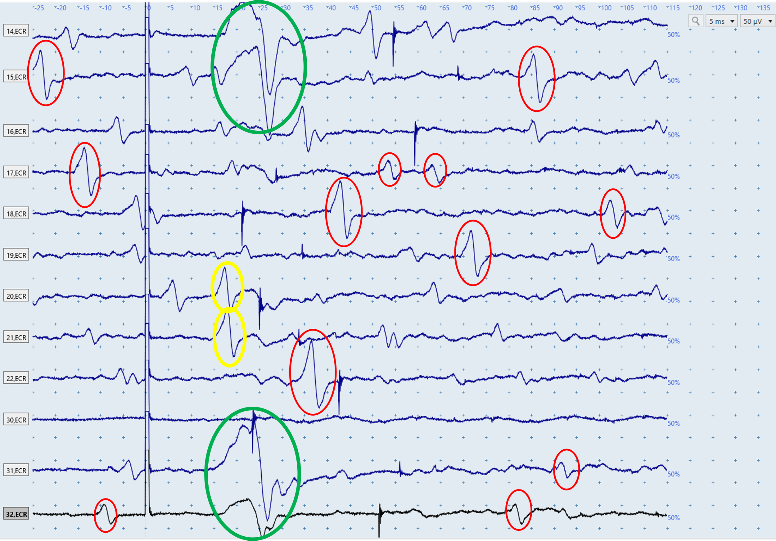
Figure K: The above figure displays a series of ECR EMG traces, each of which is the result of a single stimulation. ECR MEPs are present in the first two and last two traces (green). Numerous sporadic motor-unit responses also occur (some circled red) and can be identified by their similar shape and latencies outside the expected MEP window. There are many other motor units firing in these traces that haven't been circled. The two responses in yellow are within the expected window for ECR MEP latencies but are likely sporadic motor-unit responses because their shape is similar to the motor units firing in the red circles, and dissimilar to the MEPs in the green circles.
Electrical noise
Electrical noise may arise from poor electrode–skin contact or environmental sources such as fluorescent lighting.
Electrical noise usually has a regular pattern in EMG traces. It's important to recognize that electrical noise comes in many different shapes, such as rhythmic wave-like patterns or abrupt, sharp deflections in the EMG traces. Figures L-S below all show electrical noise issues but almost none of them show the same electrical noise.
To troubleshoot electrical noise:
Check that the ground strap or electrode contacts the skin.
Clean the ground strap with an alcohol wipe.
Check electrode contact and secure with tape if needed.
Check that the electrode leads are secure to the patient and EMG unit.
Move the ground electrode to another bony prominence.
Untangle the electrode leads.
Ensure no one touches the patient or TMS trolley during testing.
Unplug the bed from mains power.
Turn off fluorescent lighting where possible.
Increase the distance between the TMS stimulator, EMG unit, and patient.
Use a different power outlet for the TMS machine.
Use shorter electrode leads if available.
Repeat skin preparation if needed: shave, clean with alcohol, and light abrade.
If noise appears only during bilateral facilitation, reposition the leads to prevent tugging.
Electrical noise in both channels
Electrical noise in both channels indicates an issue with the grounding strap/electrode or environment. Follow the suggested troubleshooting steps above.
Non-Biological Noise
The main non-biological noise types are electrical noise in both channels, electrical noise in one channel, and prolongedstimulus artefacts.
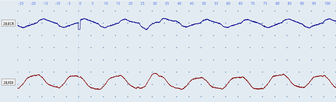
Figure L: Regular wave-like noise in both channels indicates electrical noise is present and is likely caused by a grounding or environmental source, such as contact with the patient or trolley, fluorescent lighting, or bed power.
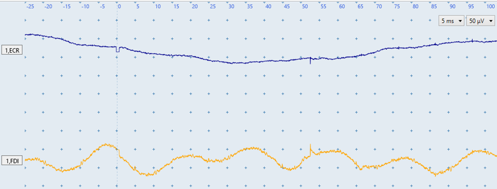
Figure M: The ECR has a drifting baseline and the FDI a sine-wave pattern. Noise in both channels again suggests a grounding or environmental source, such as interference from a person touching the TMS trolley or patient, fluorescent lighting, or electrical power supply to the bed.
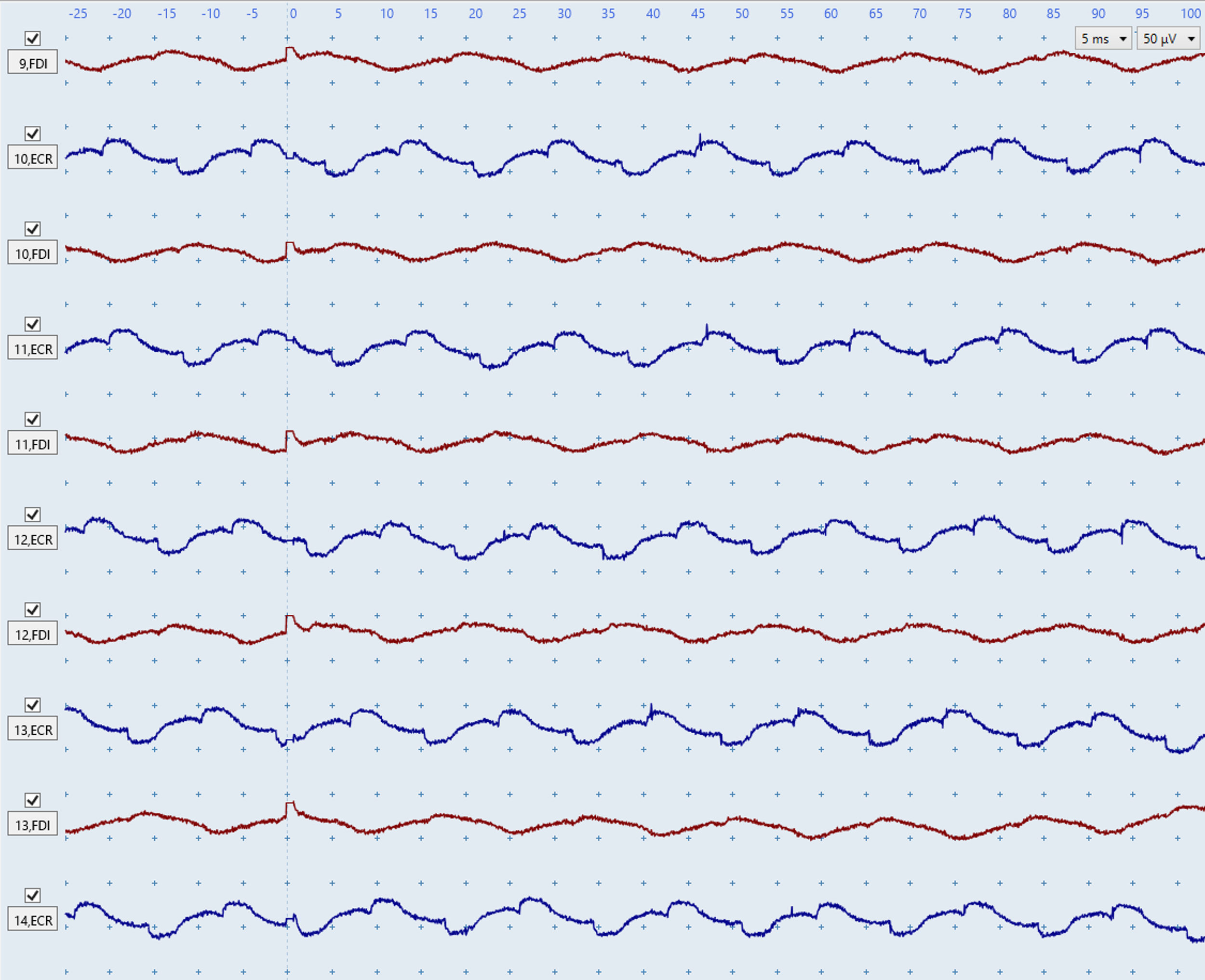
Figure N: The above figure shows a low level of rhythmic wave-like electrical noise in both channels. This figure illustrates how electrical noise is often very consistent looking between traces, in contrast to biological noise due to muscle activation which doesn't have a consistent shape as seen in Figures G-H above. Moreover, even low level electrical noise such as in figure N could obscure very small MEPs such as those present in Figure C above and lead to an incorrect MEP status determination.
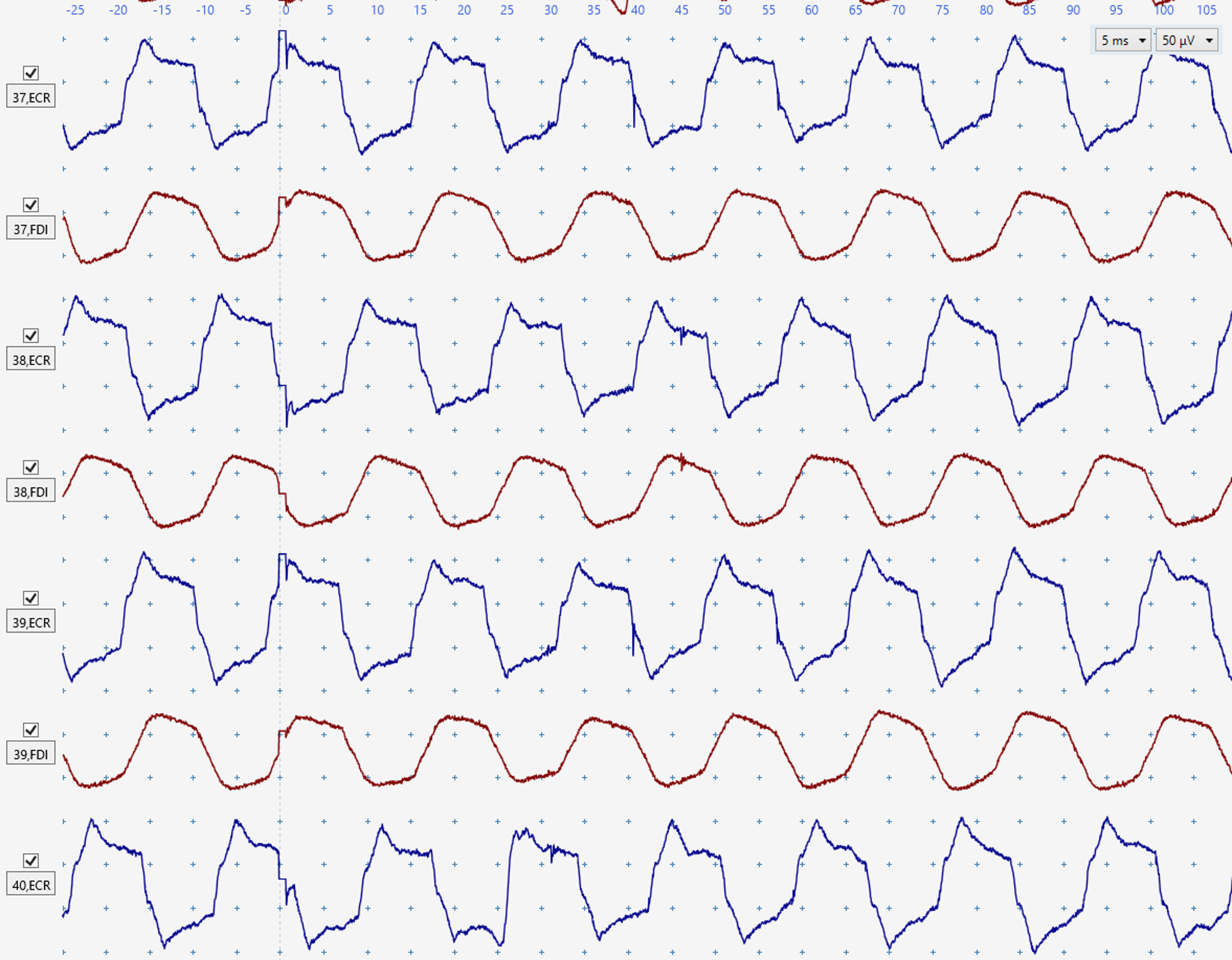
Figure O:Consistent electrical noise affects both channels which could obscure small MEPs, such as those in Figure C.
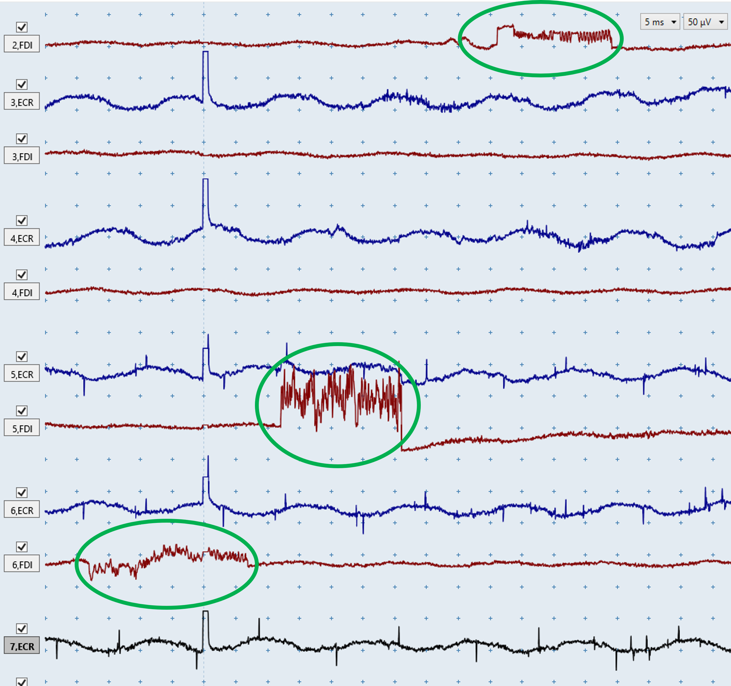
Figure P: The ECR traces show consistent electrical noise. The FDI traces show occasional abrupt, unnatural deflections (green), which are characteristic of electrical noise.
Electrical noise in one channel
Electrical noise in only one muscle indicates the issue is specific to the EMG setup for that muscle such as loose or faulty cable, poor electrode contact with the skin, or a faulty electrode. To identify the source, swap the electrode leads between muscles. This will involve unclipping the cables from the electrodes of one muscle and connecting them to the electrodes of the other muscle.
If the noise remains on the same screen channel after swapping muscles, replace the leads.
If the noise moves to the other channel, repeat skin preparation and replace the affected electrode.
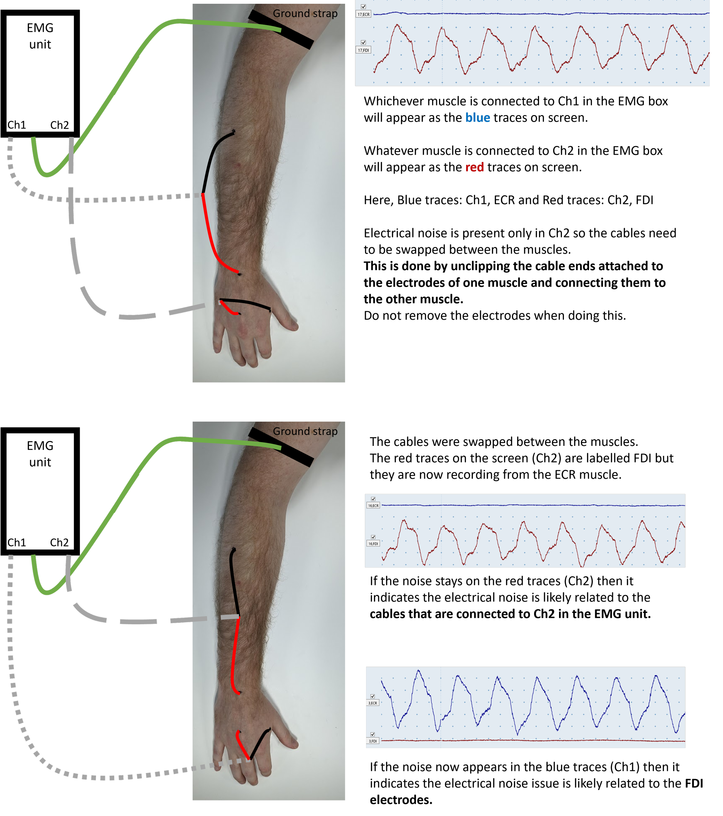
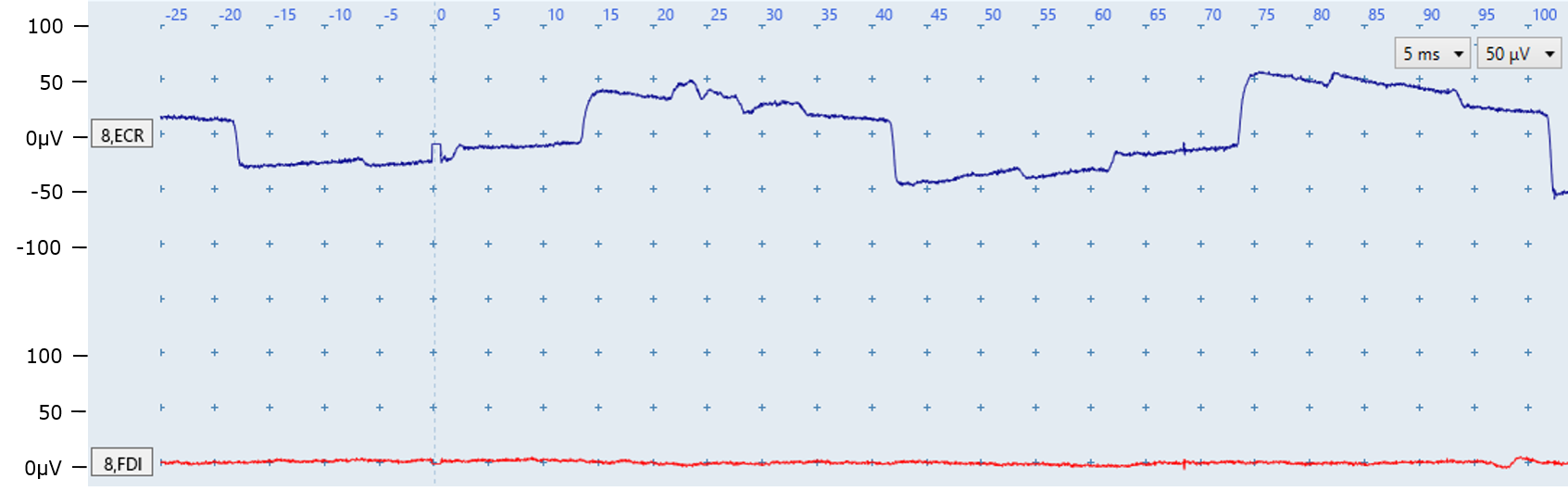
Figure Q: Regular electrical noise indicates a poor contact or faulty electrode for the ECR. A small ECR MEP may be present at ~20ms but the electrical noise obscures it. Note that the FDI is noise-free.
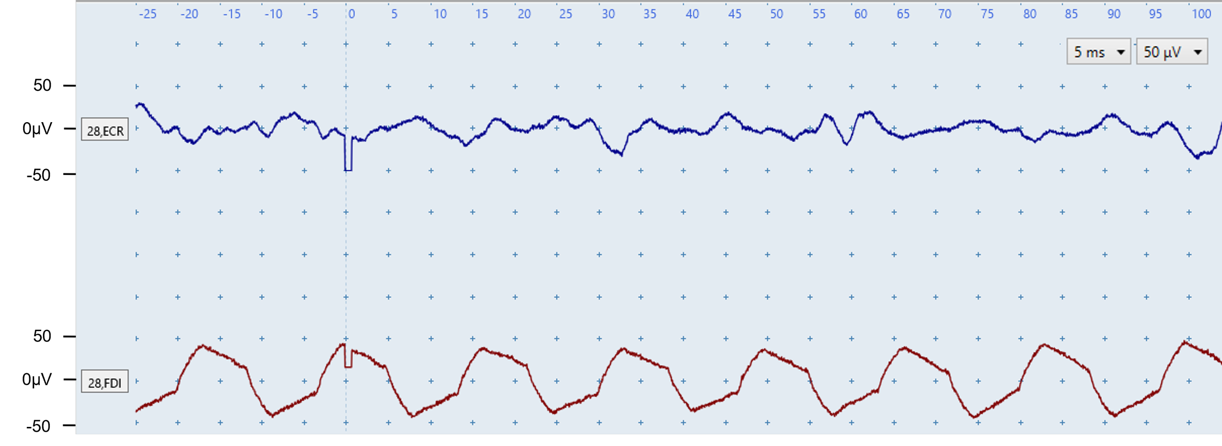
Figure R: The FDI EMG trace (bottom) is contaminated by electrical noise which you can tell by the regular pattern. The electrical noise is only present in one channel so is likely casued by a loose lead, poor contact with skin, or a faulty electrode for that channel only. The ECR contains irregular muscle-activation noise rather than electrical noise.
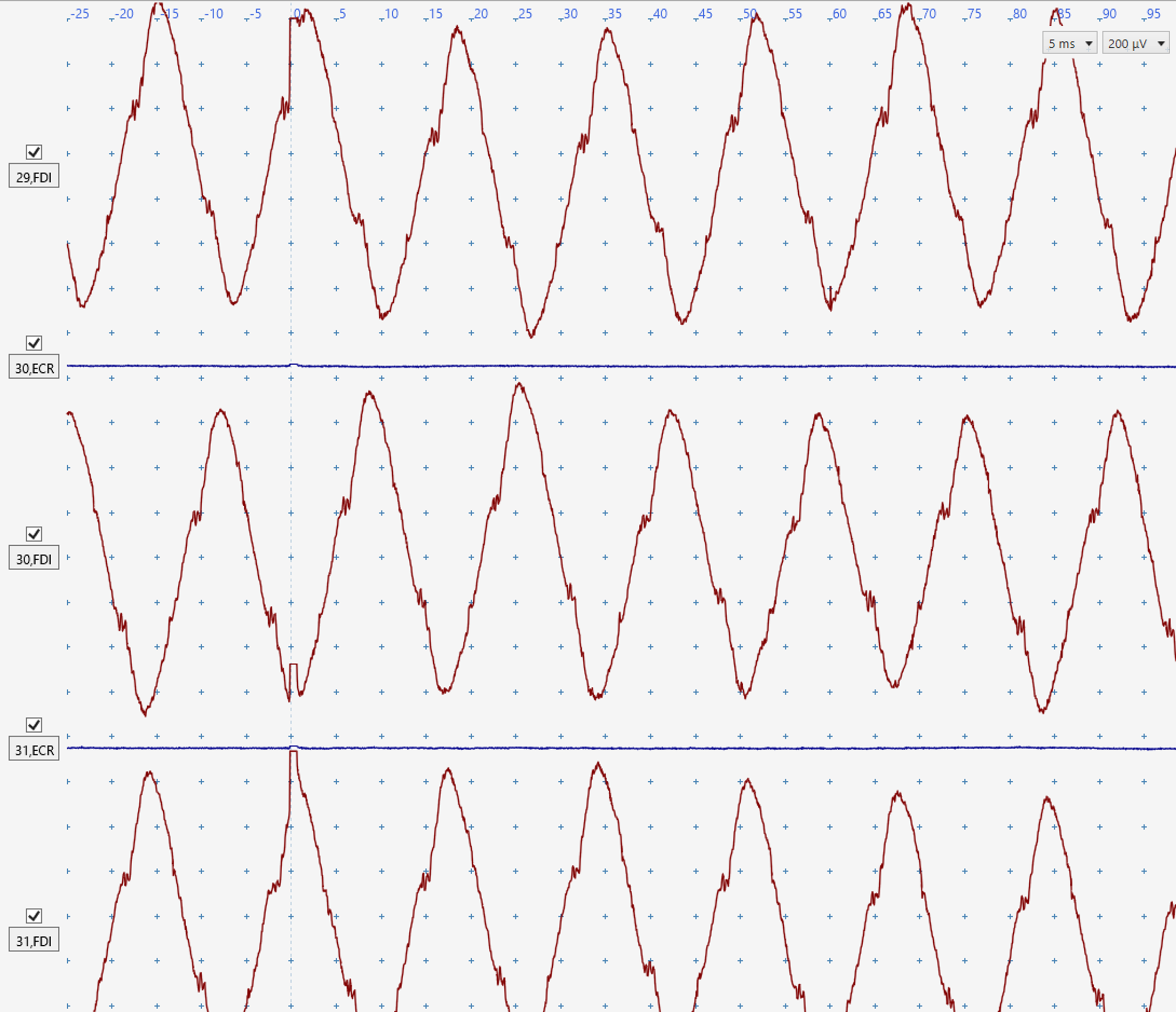
Figure S: There is electrical noise with a regular pattern in the FDI traces. The noise is likely to be caused by a loose lead, poor electrode conduction due to lack of contact with skin, or a faulty electrode. It would be difficult to detect any FDI MEPs that may be present. The ECR traces are free from noise.
Prolonged stimulus artefacts
The second form of electrical noise is a prolonged stimulus artefact of the TMS trigger that overlaps with the expected onset of the MEP and potentially obscures MEPs present. The stimulus artefact may be reduced by following the troubleshooting advice for electrical noise issues listed at the start of this section.
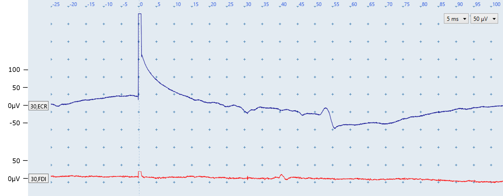
Figure T: Key features
A prolonged stimulus artefact is present in the ECR trace because the trace does not return to baseline until ~20 ms after stimulation. In contrast, the FDI ECR returns to baseline a few milliseconds after stimulation as expected.
The fluctuation seen in the ECR EMG trace at around 50 ms is most likely a motor unit firing sporadically. It is identified by its appearance at a latency which does not correspond with the expected latency between 15 and 25 ms for ECR MEPs.
The fluctuation seen in the FDI EMG trace at around 40 ms is also not a MEP, and is also most likely a motor unit firing sporadically.
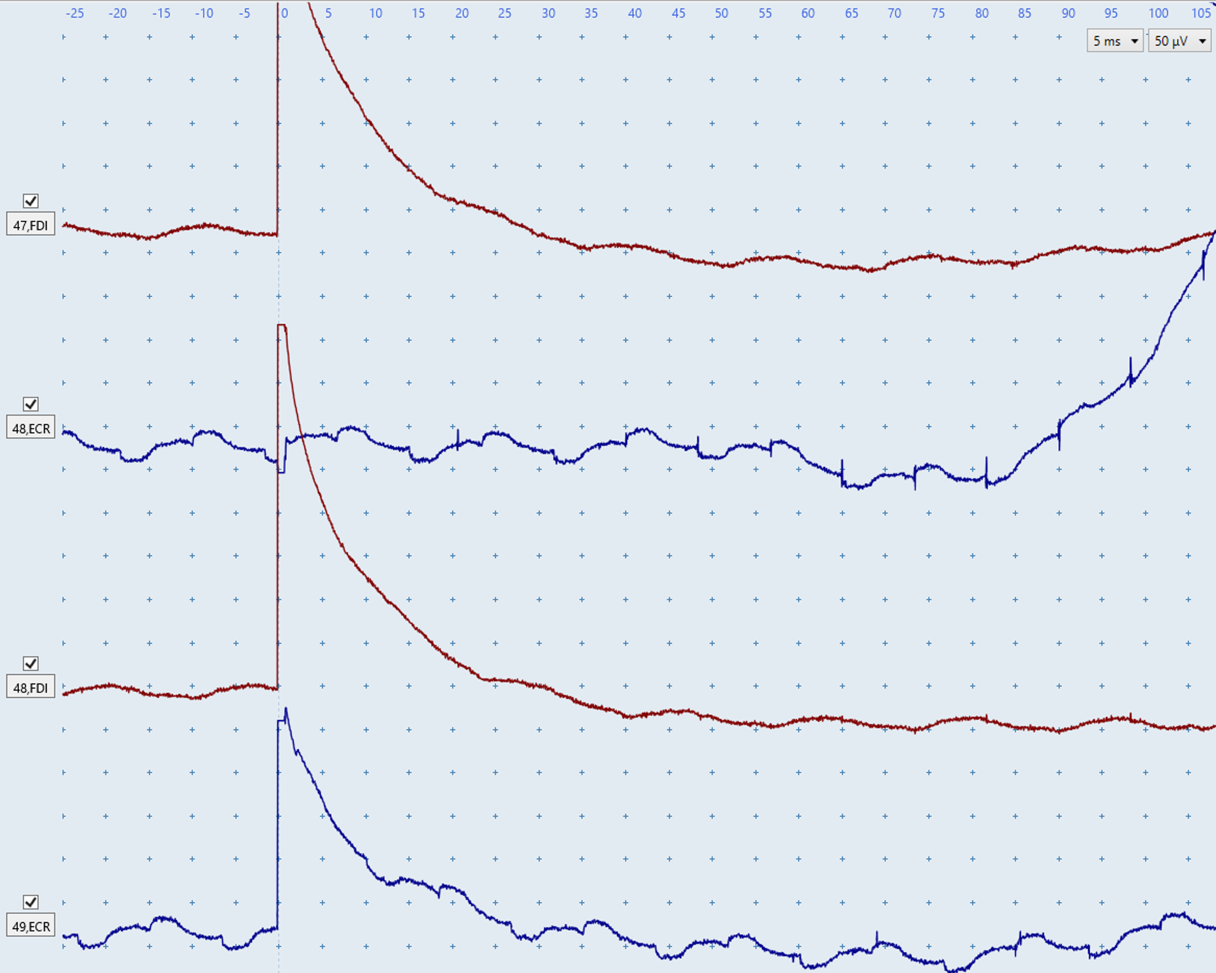
Figure U: Both FDI traces have prolonged artefacts, returning to baseline at ~30 ms.
The upper blue ECR trace does not have a prolonged stimulus artefact, however an electrical noise issue is present due to the consistent nature of the noise. The abrupt upwards deflection starting at ~85 ms is indicative of a general electrical noise issue.
The bottom blue ECR trace contains the same electrical noise issue as the top trace in addition to a prolonged stimulus artefact that only returns to baseline at ~25 ms.
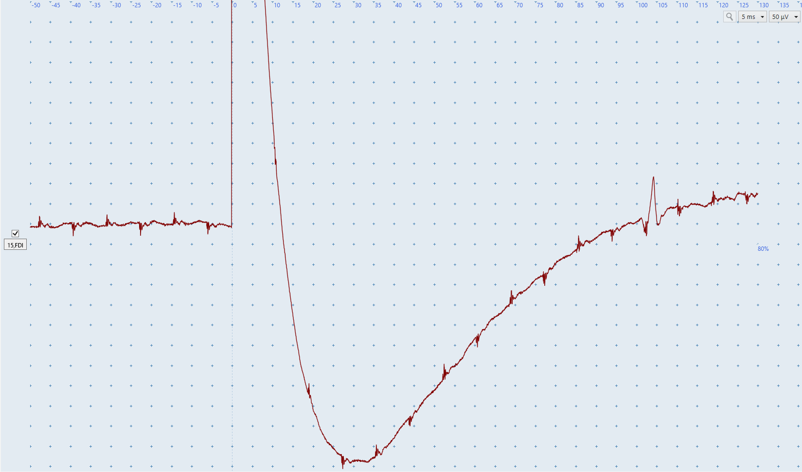
Figure V: A prolonged stimulus artefact is present in the FDI EMG trace as it only returns to baseline at ~120 ms. A spontaneous motor-unit firing is also present at ~100ms.
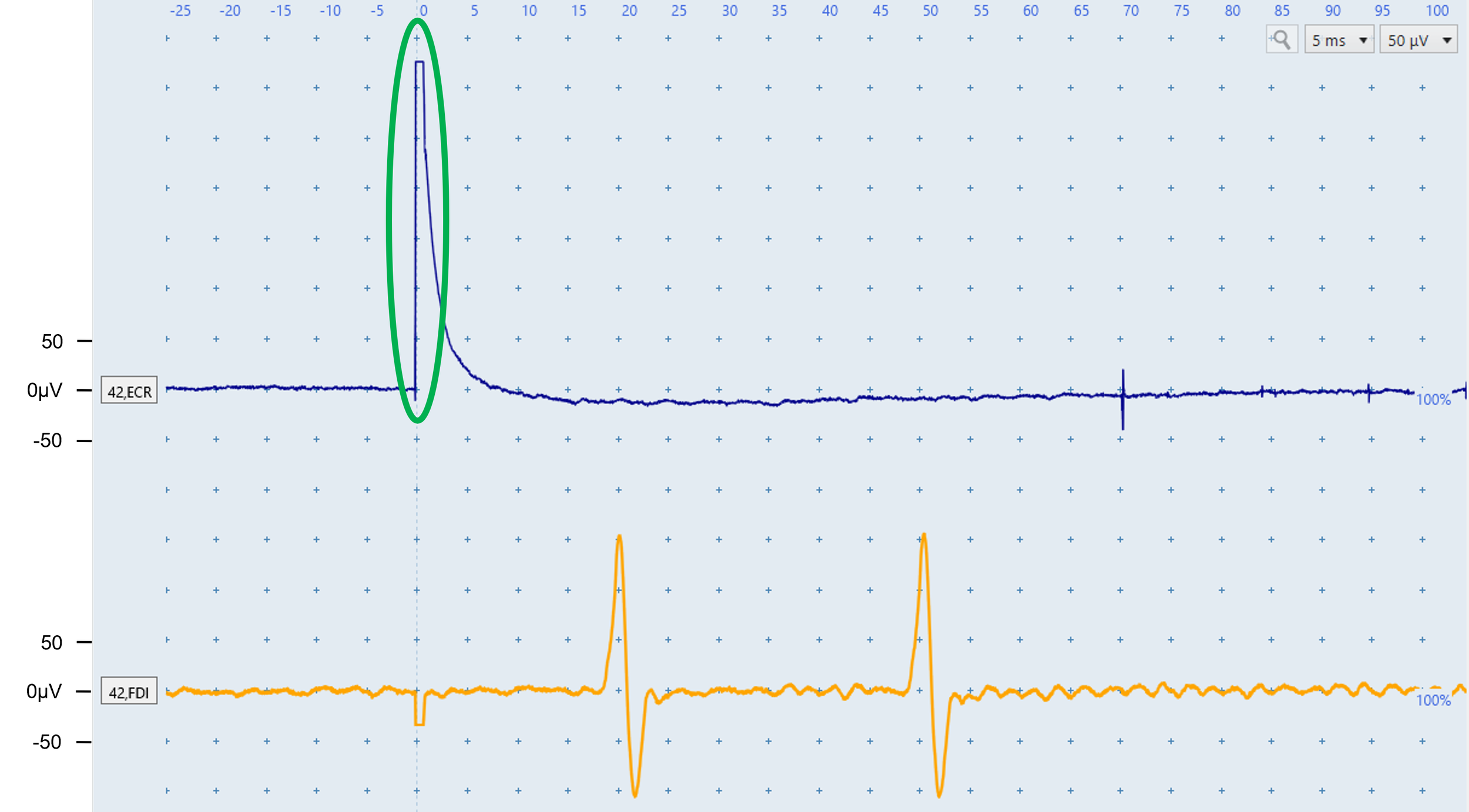
Figure W: The ECR artefact is large (~325 microvolts) but not prolonged because baseline returns by ~8 ms. This would not be considered a prolonged stimulus artefact.
The yellow FDI trace contains two likely motor-unit responses. Although the ~18 ms deflection lies within the MEP window, its identical shape and amplitude to the ~48 ms response indicate sporadic firing. Similar responses across traces would strengthen this interpretation; Figure I shows a similar situation of two motor units firing despite one of them being in the appropriate latency range for FDI MEPs.
FAQs
What if the patient cannot relax and low-level muscle activity remains?
1
Reposition and support the arms, cue shoulder relaxation, offer a break, distract from the procedure, or begin with low-intensity stimulation. If activity persists, continue and identify MEPs within the noise; biological noise makes classification harder but should not prevent it. See Module 6 Challenging MEP Identification for examples.
How can I distinguish a motor-unit response from an MEP?
2
Compare latency, shape, and recurrence of deflections across traces. Responses outside the expected window are very unlikely to be MEPs. Sporadic motor-unit responses recur with highly consistent shape and size; MEPs occur once within the expected window and vary more between traces. An MEP+ classification is still possible in the presence of motor-unit firing.
Should I still attempt to complete the test if I am unable to fully resolve all noise issues?
3
MEP status may still be determined when MEPs clearly exceed the noise and recur across traces. Before classifying MEP−, make every effort to obtain noise-free EMG within the expected latency window. If no MEP is found and noise persists, seek another operator’s help, reschedule, or test in a different environment.
Quiz
Complete the practice quiz
Score at least 70% to receive the final quiz link by email.
Score at least 80% on the final quiz to receive a certificate of completion. Attempts are unlimited.